> ## Documentation Index
> Fetch the complete documentation index at: https://docs.robot-learning.co/llms.txt
> Use this file to discover all available pages before exploring further.
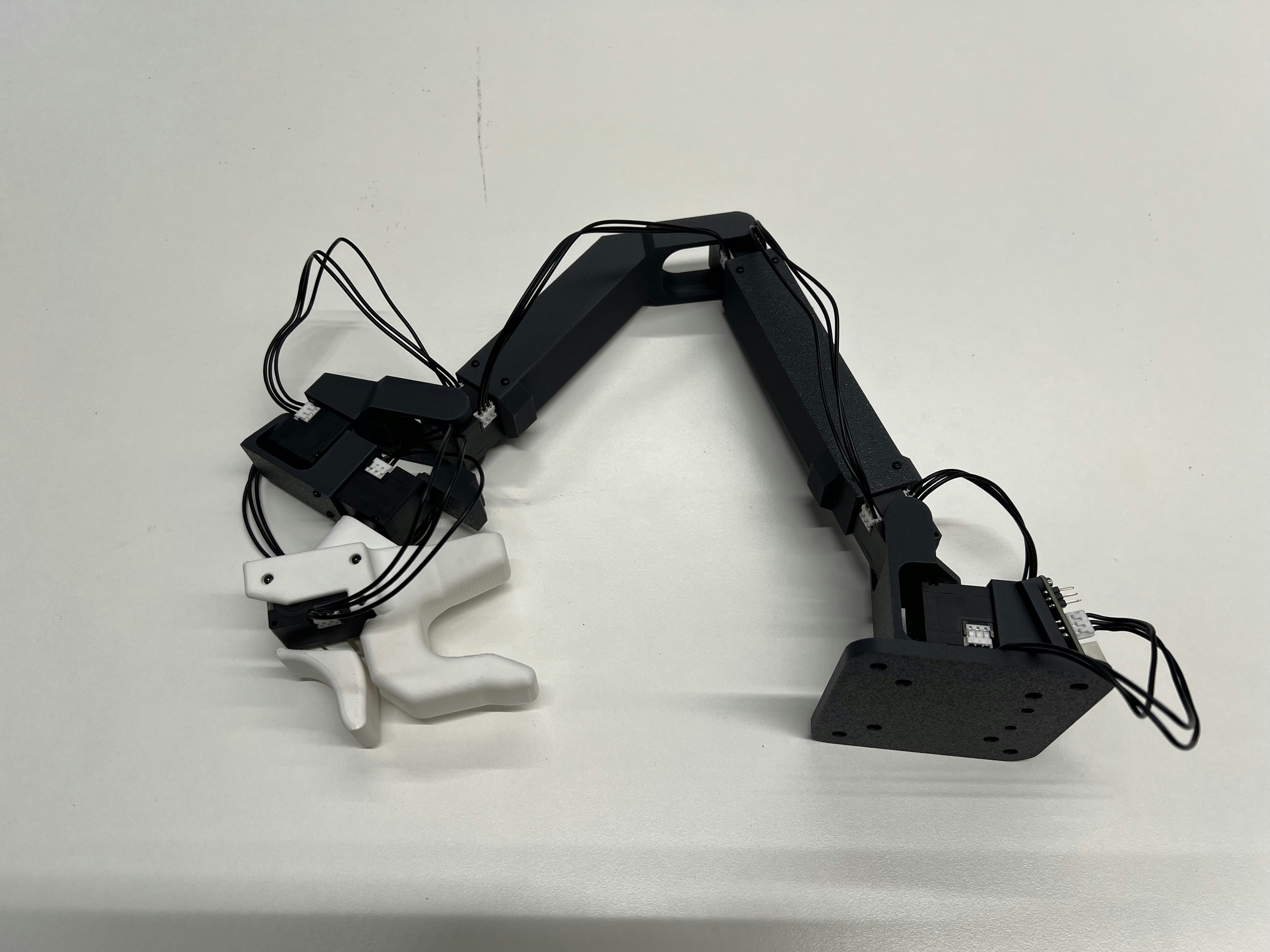
# Leader Arm Assembly
> How to assemble or repair DK1's open-source passive leader arm.
Please note: if you buy a kit from The Robot Learning Company, it will be shipped to you fully assembled and calibrated.
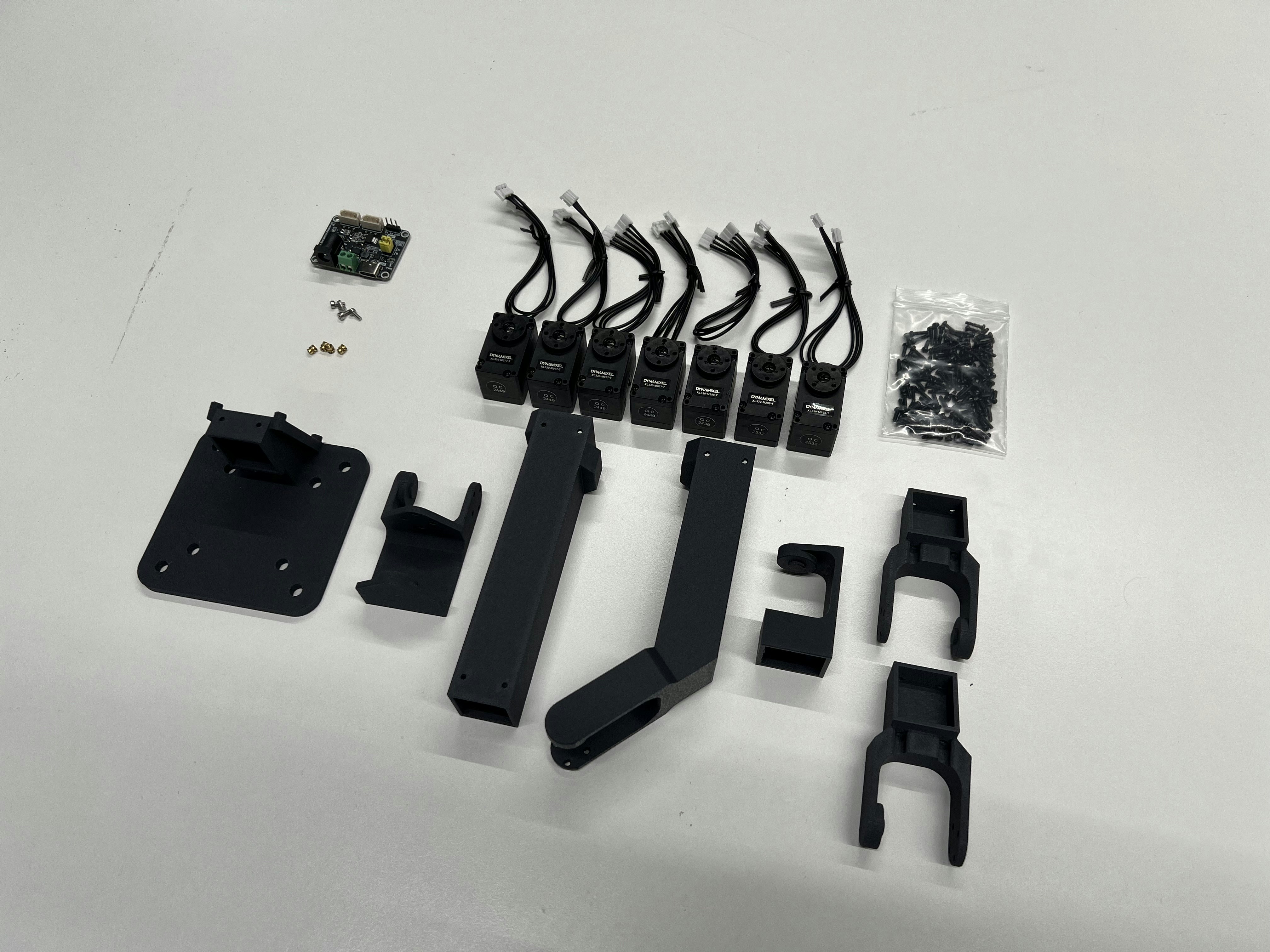 ## Components
| Part Name | Qty | Source |
| ------------------------------------------------- | --- | ------------------------------------------------------------------- |
| Dynamixel XL330-M077-T | 7 | [https://en.robotis.com/shop\_en/](https://en.robotis.com/shop_en/) |
| Waveshare Serial Bus Servo Driver Board | 1 | [https://www.amazon.com/](https://www.amazon.com/) |
| 3D-printed Links using PLA(-CF) | | [https://store.bambulab.com/](https://store.bambulab.com/) |
| 5V DC Power Supply (2 Pole or 5.5x2.1 Power Jack) | 1 | [https://www.amazon.com/](https://www.amazon.com/) |
| M2x4 Inserts | 4 | [https://www.amazon.com/](https://www.amazon.com/) |
| M2x5 Screws (e.g. ISO 4762) | 4 | [https://www.amazon.com/](https://www.amazon.com/) |
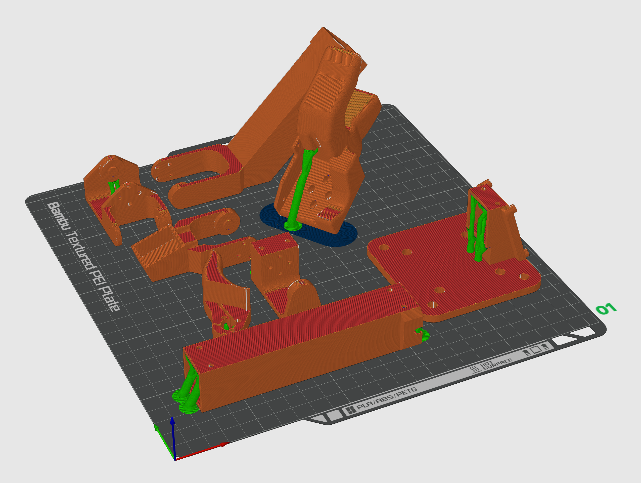
## 3D Printing
All .STL files and a Bambu Lab 3MF project file are located in the [TRLC-DK1 GitHub Repo](https://github.com/robot-learning-co/trlc-dk1/tree/24a30ab8782e83a1143aef73c3ce62515690ee49/hardware/leader_STLs).
**Recommended 3D-printing orientation:**
{" "}
## Components
| Part Name | Qty | Source |
| ------------------------------------------------- | --- | ------------------------------------------------------------------- |
| Dynamixel XL330-M077-T | 7 | [https://en.robotis.com/shop\_en/](https://en.robotis.com/shop_en/) |
| Waveshare Serial Bus Servo Driver Board | 1 | [https://www.amazon.com/](https://www.amazon.com/) |
| 3D-printed Links using PLA(-CF) | | [https://store.bambulab.com/](https://store.bambulab.com/) |
| 5V DC Power Supply (2 Pole or 5.5x2.1 Power Jack) | 1 | [https://www.amazon.com/](https://www.amazon.com/) |
| M2x4 Inserts | 4 | [https://www.amazon.com/](https://www.amazon.com/) |
| M2x5 Screws (e.g. ISO 4762) | 4 | [https://www.amazon.com/](https://www.amazon.com/) |
## 3D Printing
All .STL files and a Bambu Lab 3MF project file are located in the [TRLC-DK1 GitHub Repo](https://github.com/robot-learning-co/trlc-dk1/tree/24a30ab8782e83a1143aef73c3ce62515690ee49/hardware/leader_STLs).
**Recommended 3D-printing orientation:**
{" "}
 **Recommended 3D-printing settings:**
* Material: PLA-CF
* Nozzle: 0.4mm
* Layer height: 0.12mm
* Infill: 15%, Gyroid
* Support: On
If you're using a Bambu Lab 3D printer, use the **0.12mm High Quality** Setting
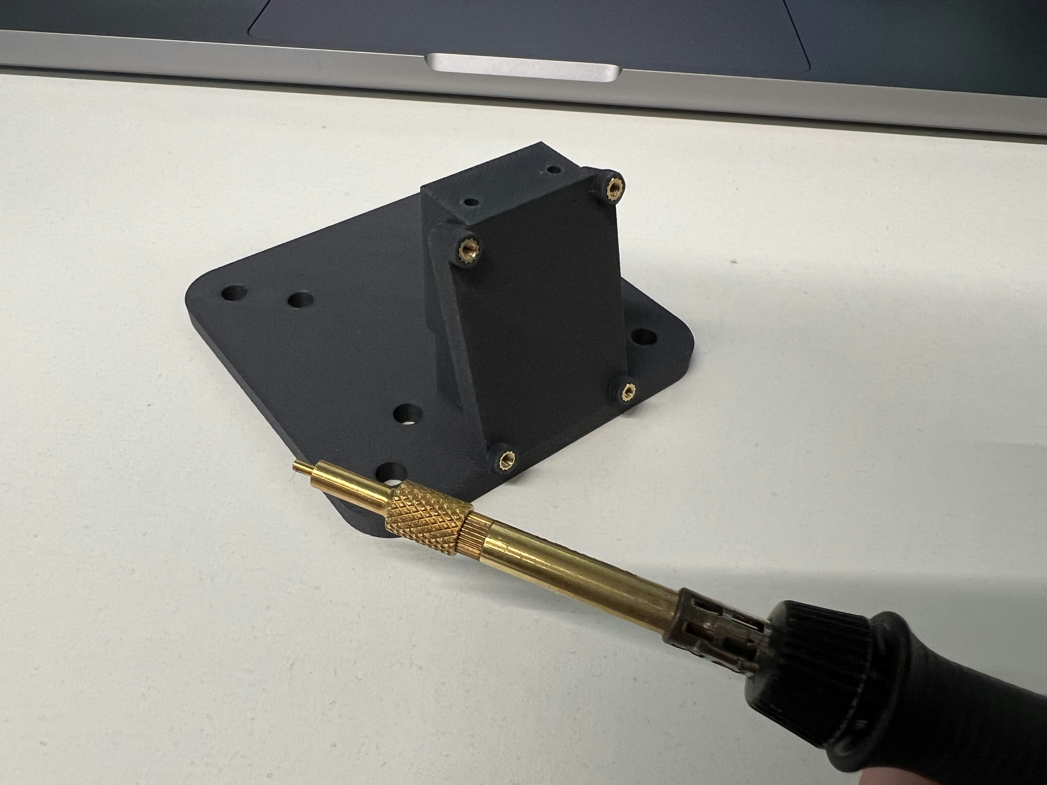
## Assembly
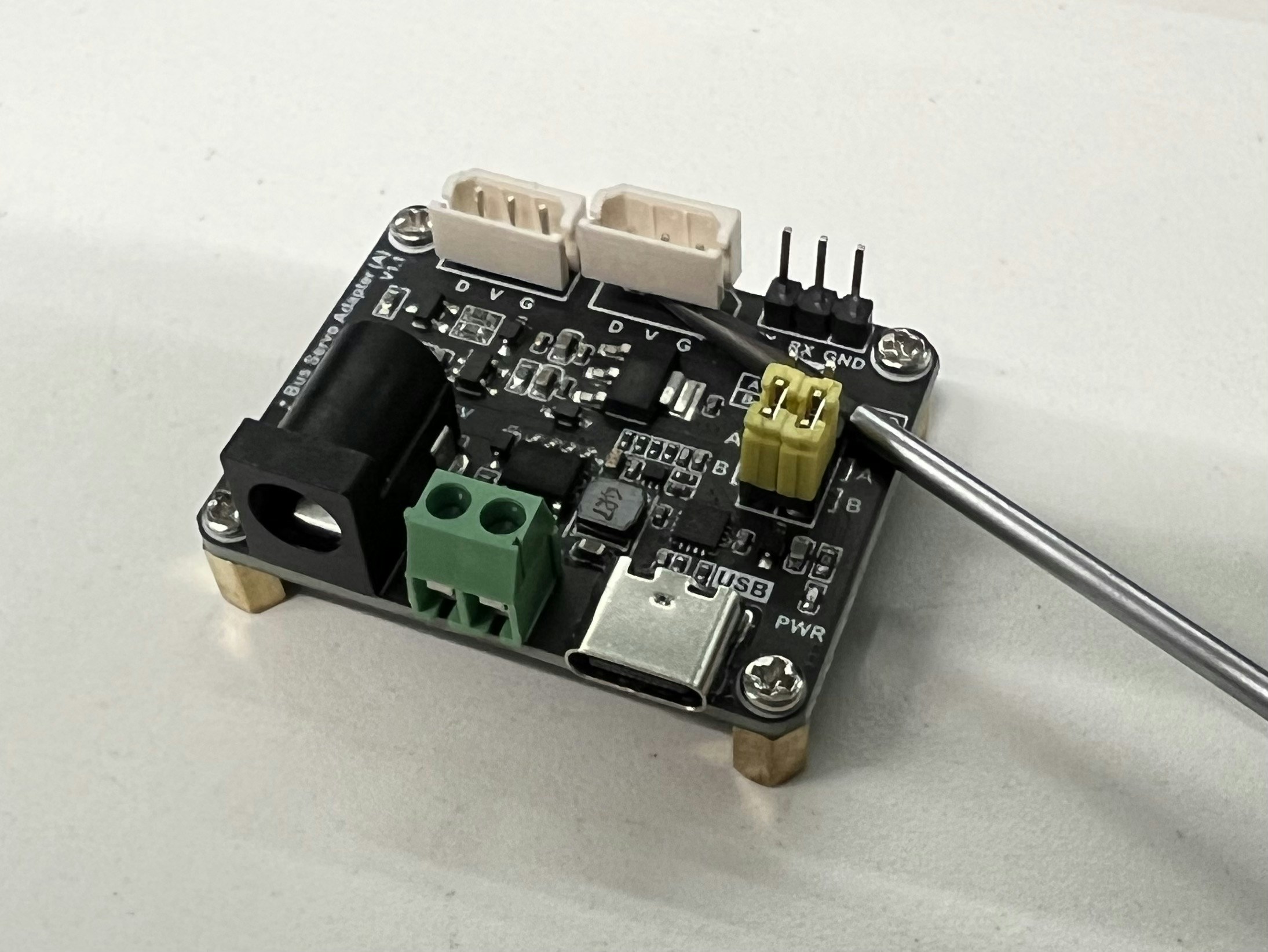
First, install the inserts and gently remove one of the 3-pin header cap from the driver board:
**Recommended 3D-printing settings:**
* Material: PLA-CF
* Nozzle: 0.4mm
* Layer height: 0.12mm
* Infill: 15%, Gyroid
* Support: On
If you're using a Bambu Lab 3D printer, use the **0.12mm High Quality** Setting
## Assembly
First, install the inserts and gently remove one of the 3-pin header cap from the driver board:
 Every Dynamixel frame is mounted using **4 long screws**, every output horn using **4 short screws**:
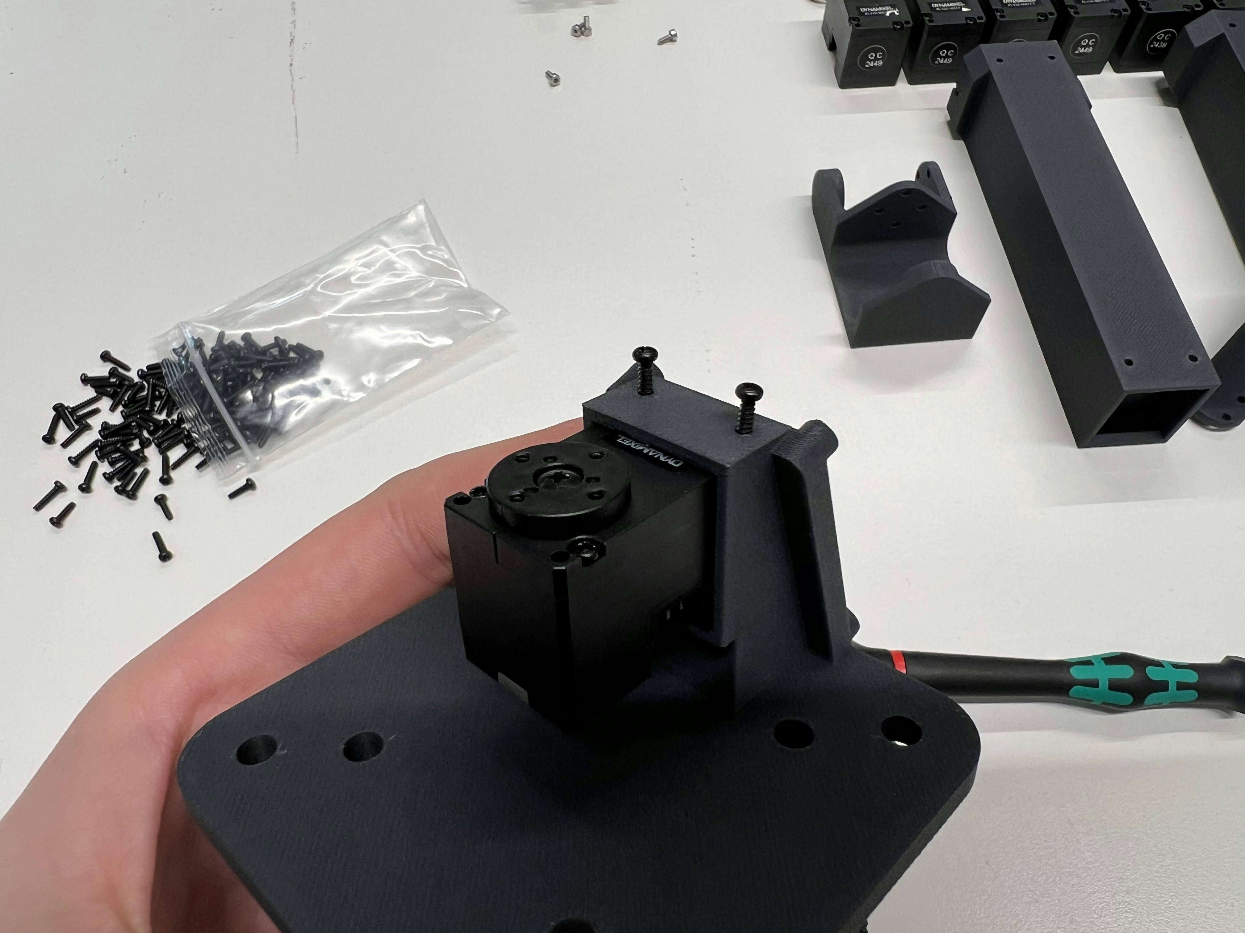
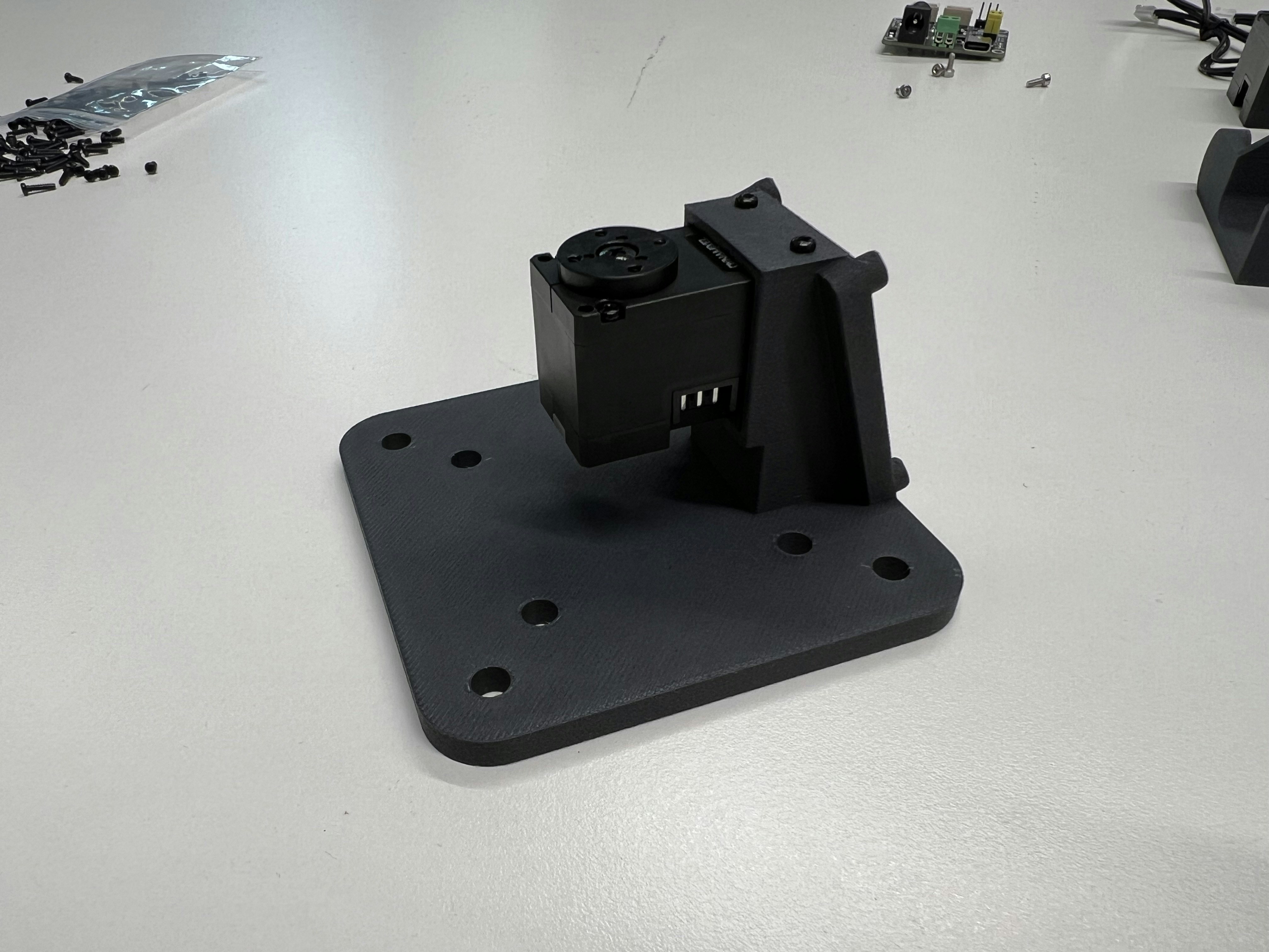
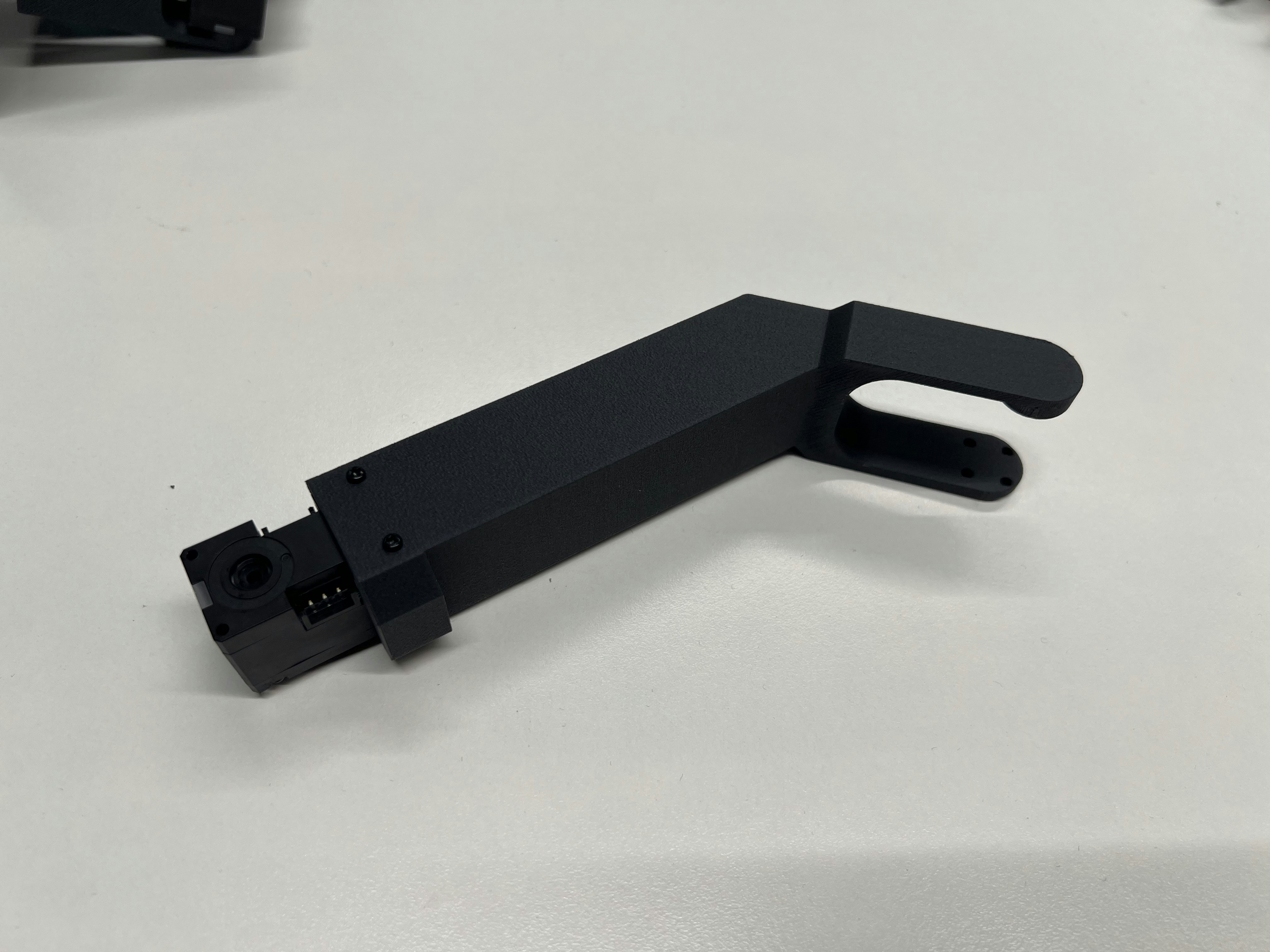
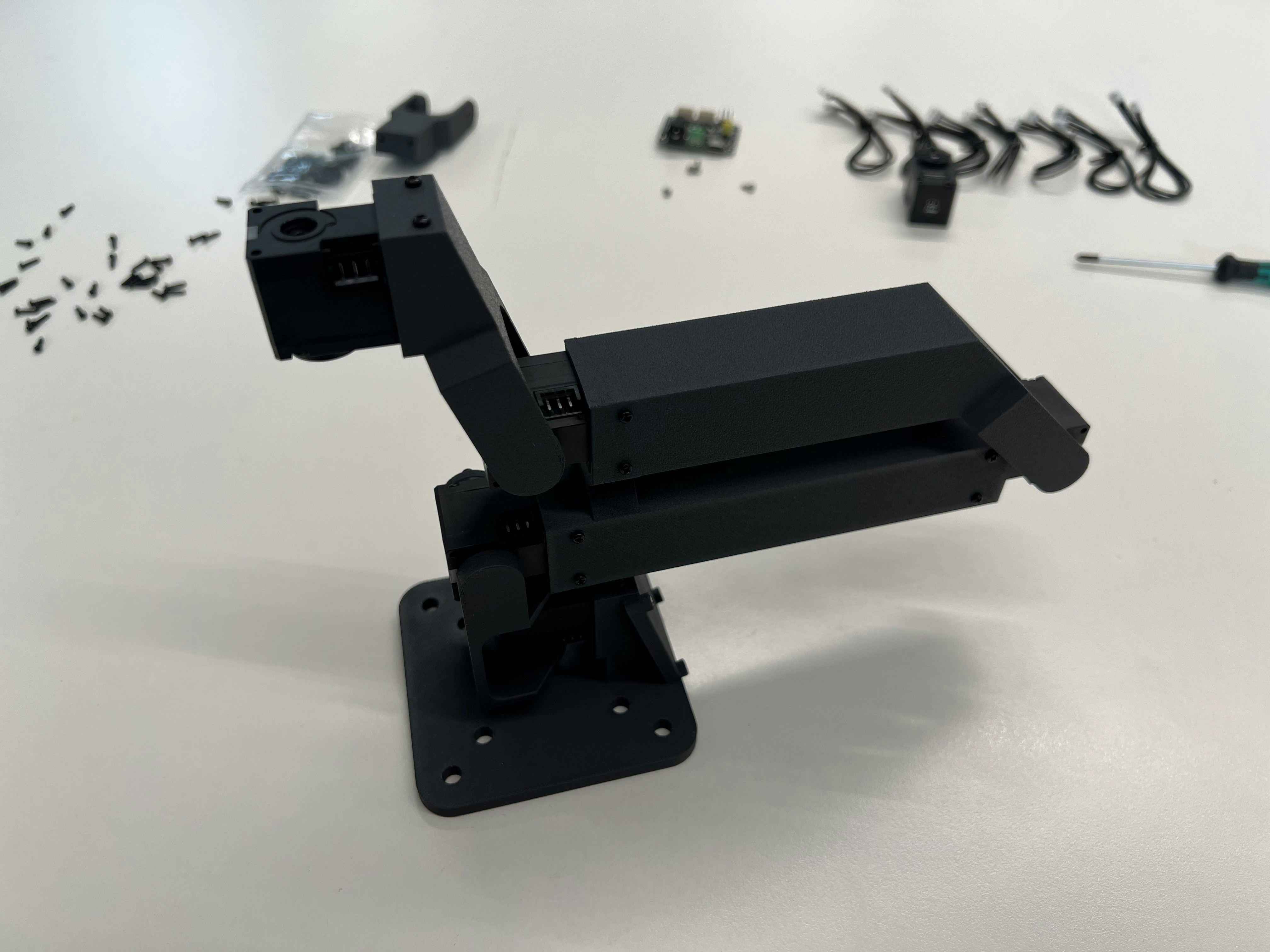
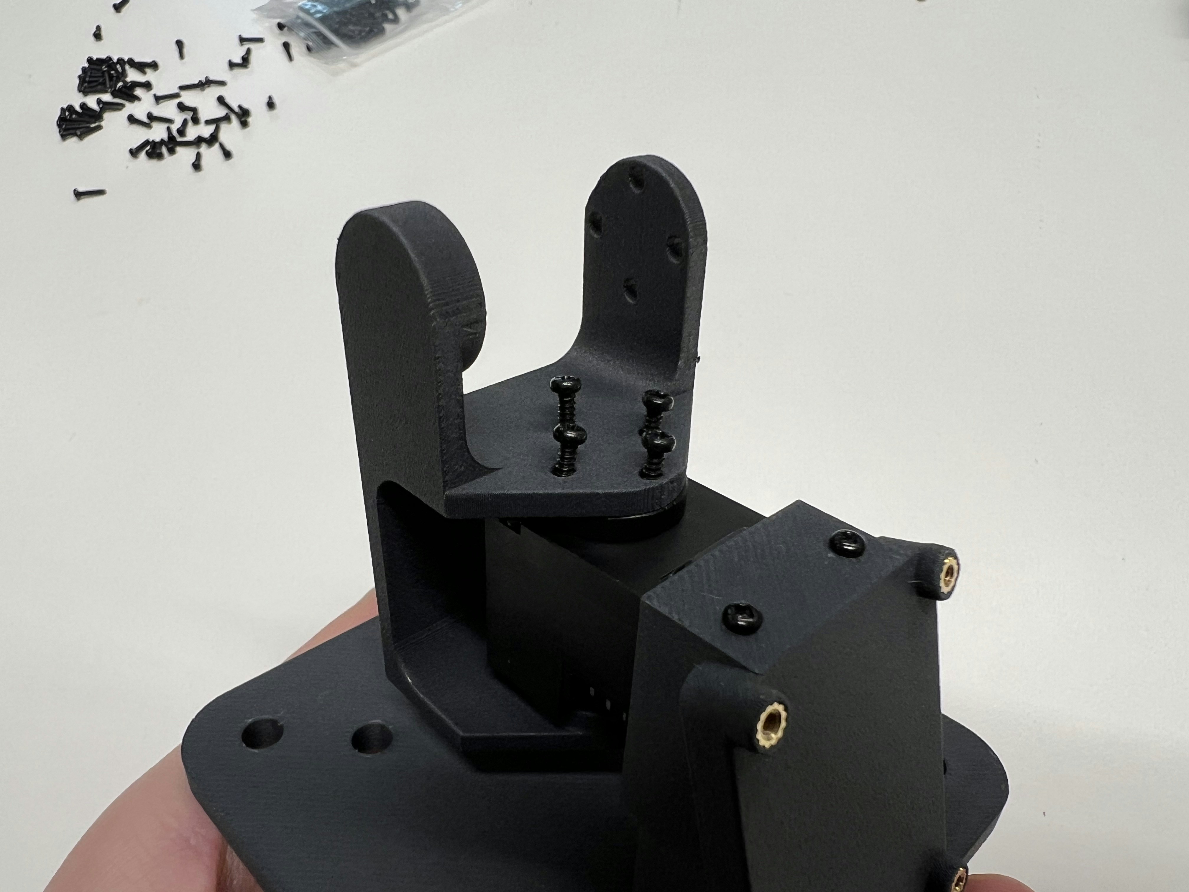 For less calibration pain afterwards, assemble all parts in the Dynamixel's absolute zero position (marked by the engraved lines):
 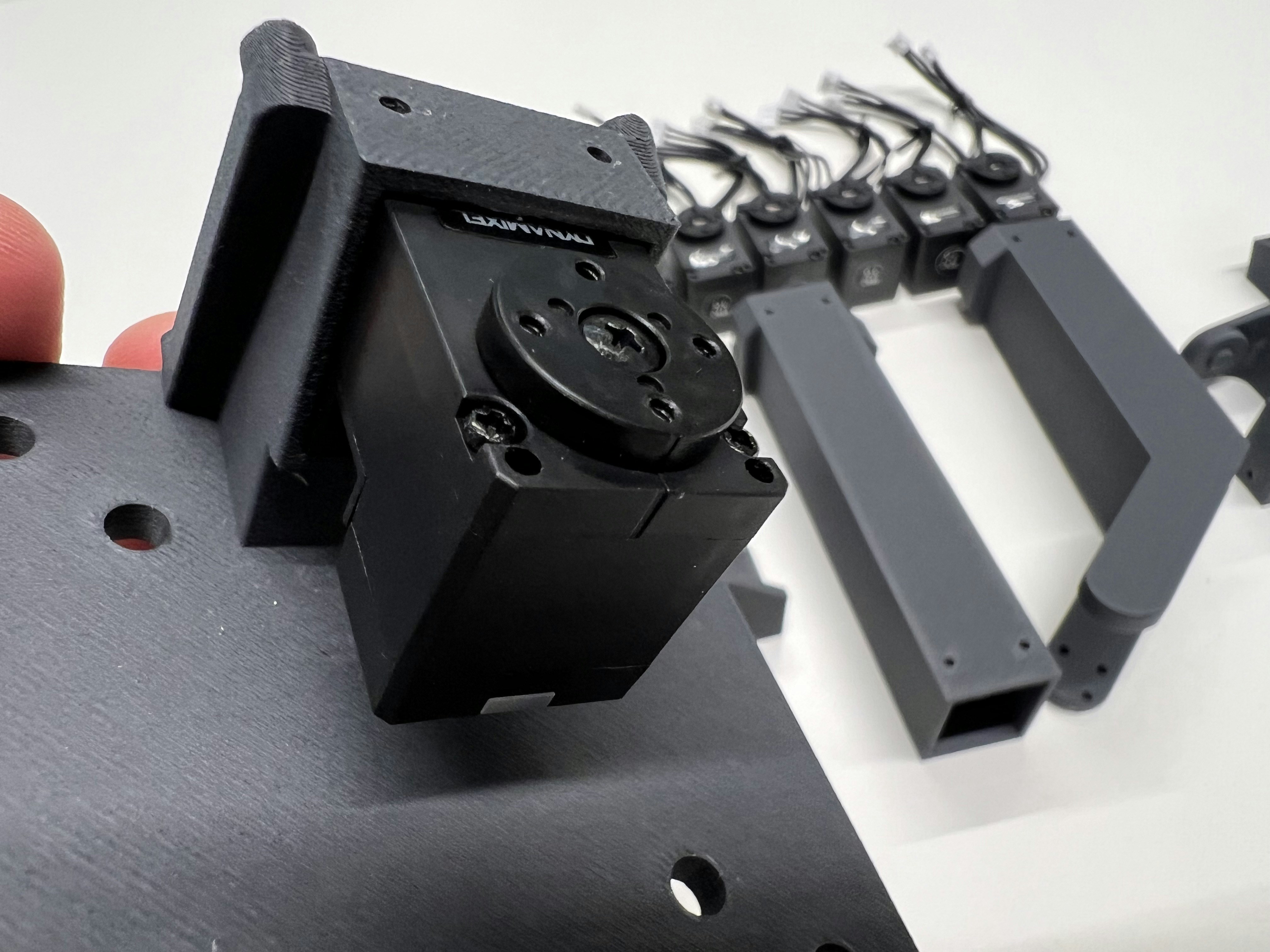 Assemble as shown:
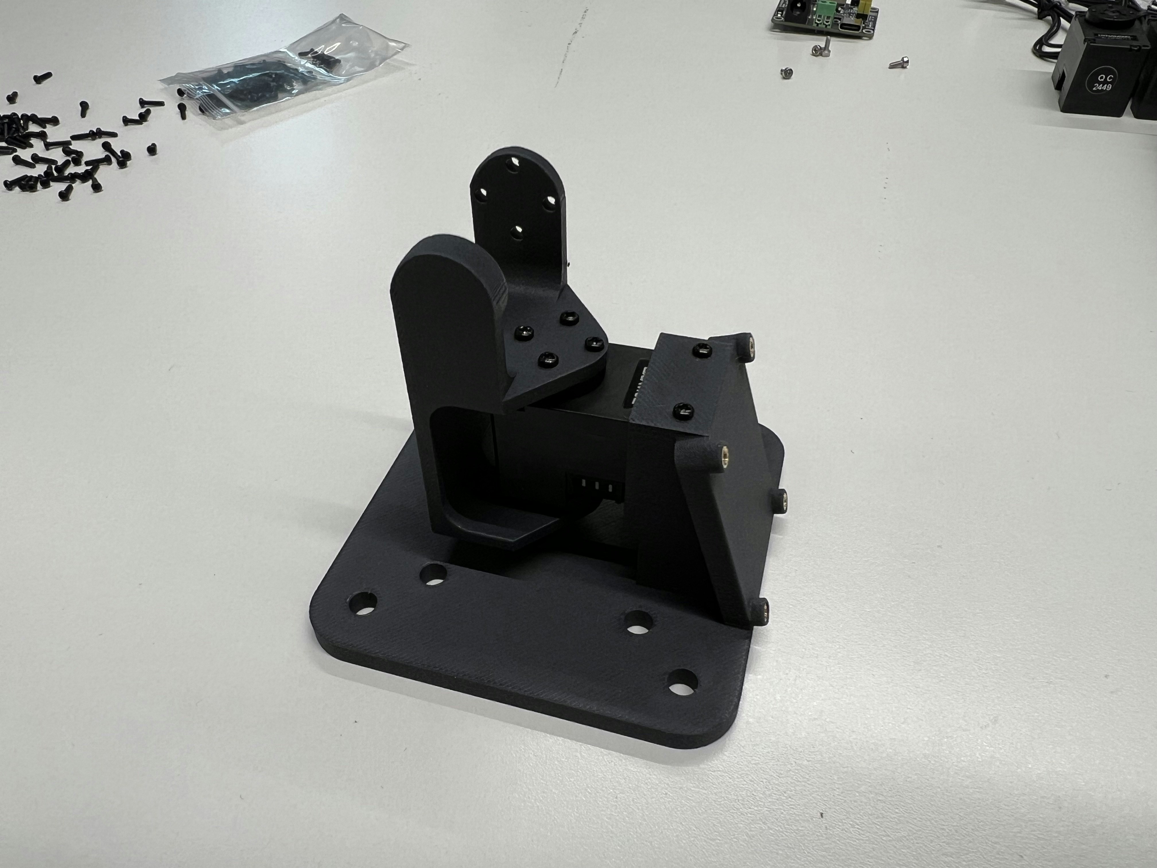
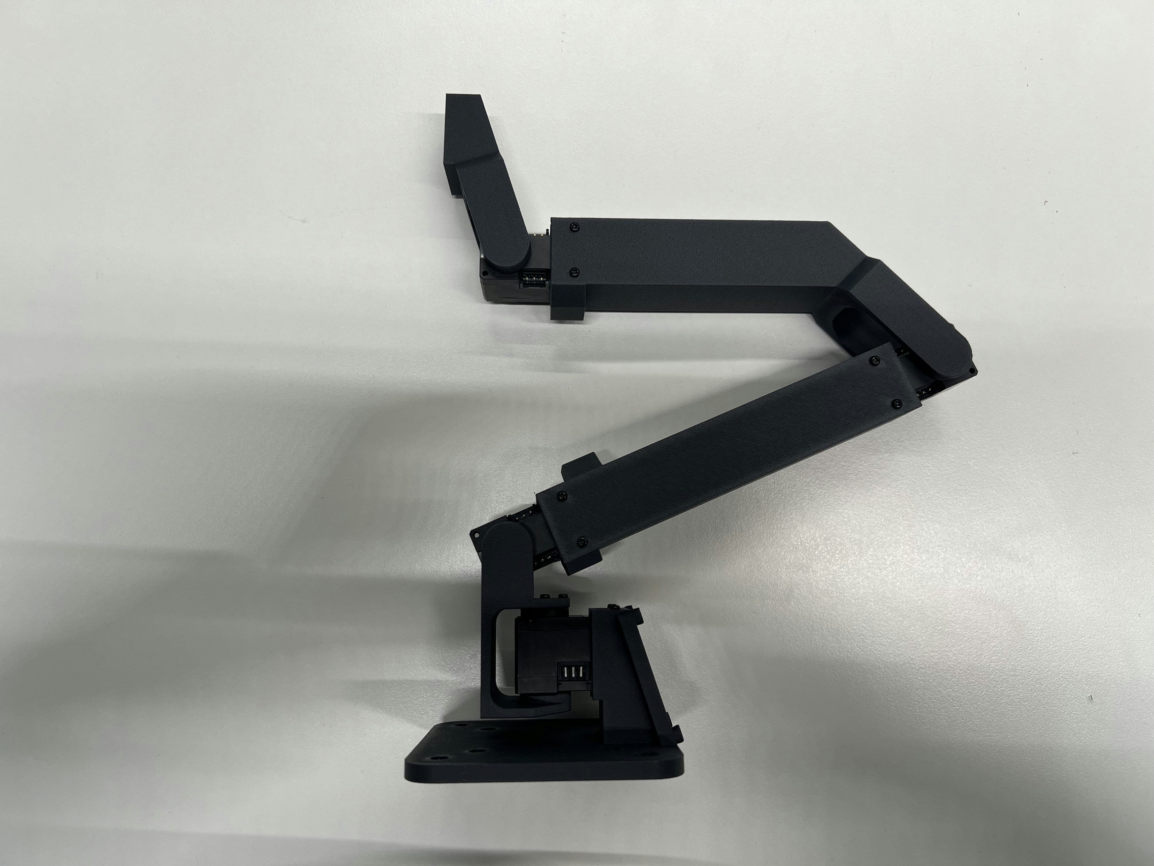
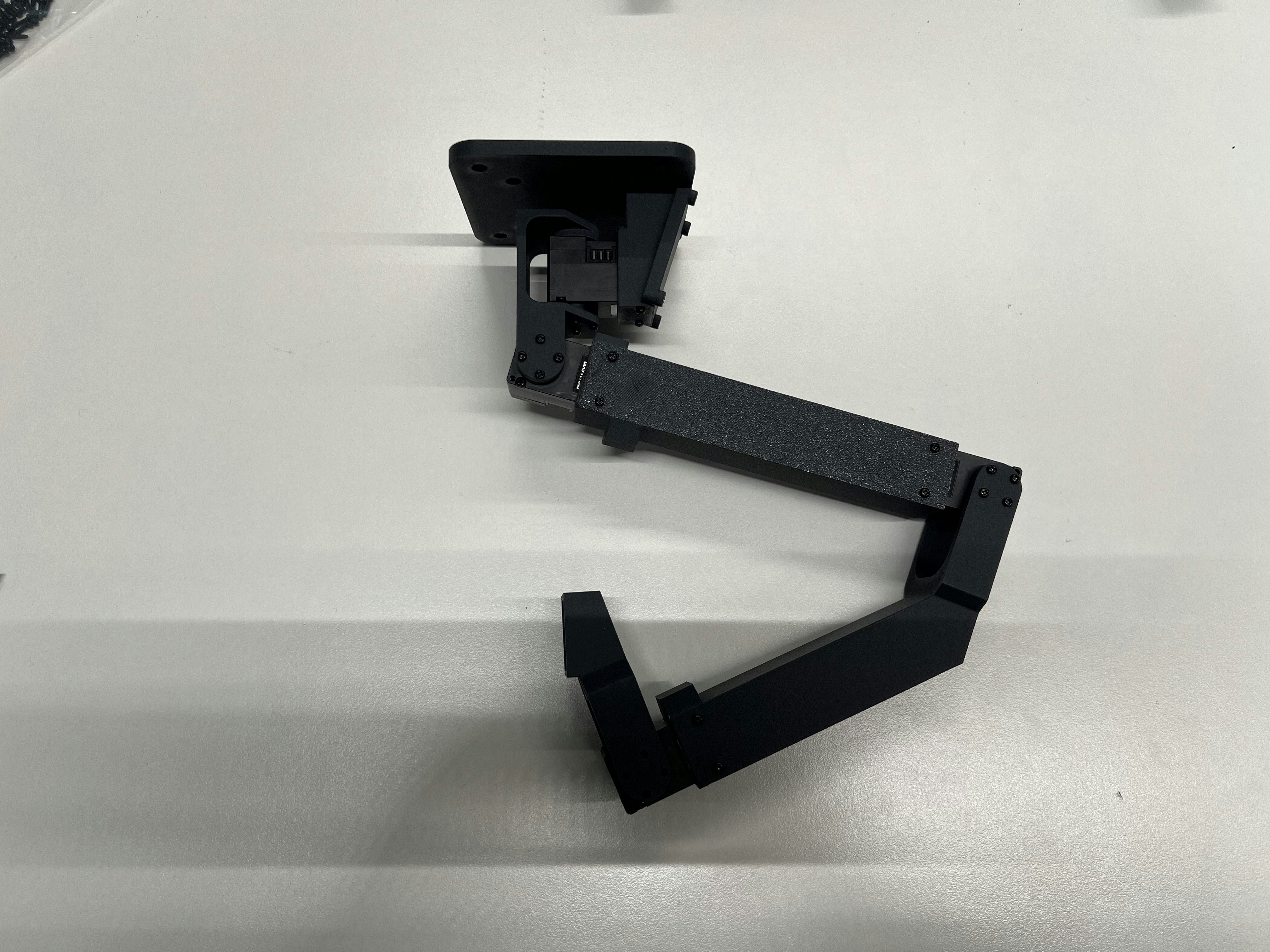
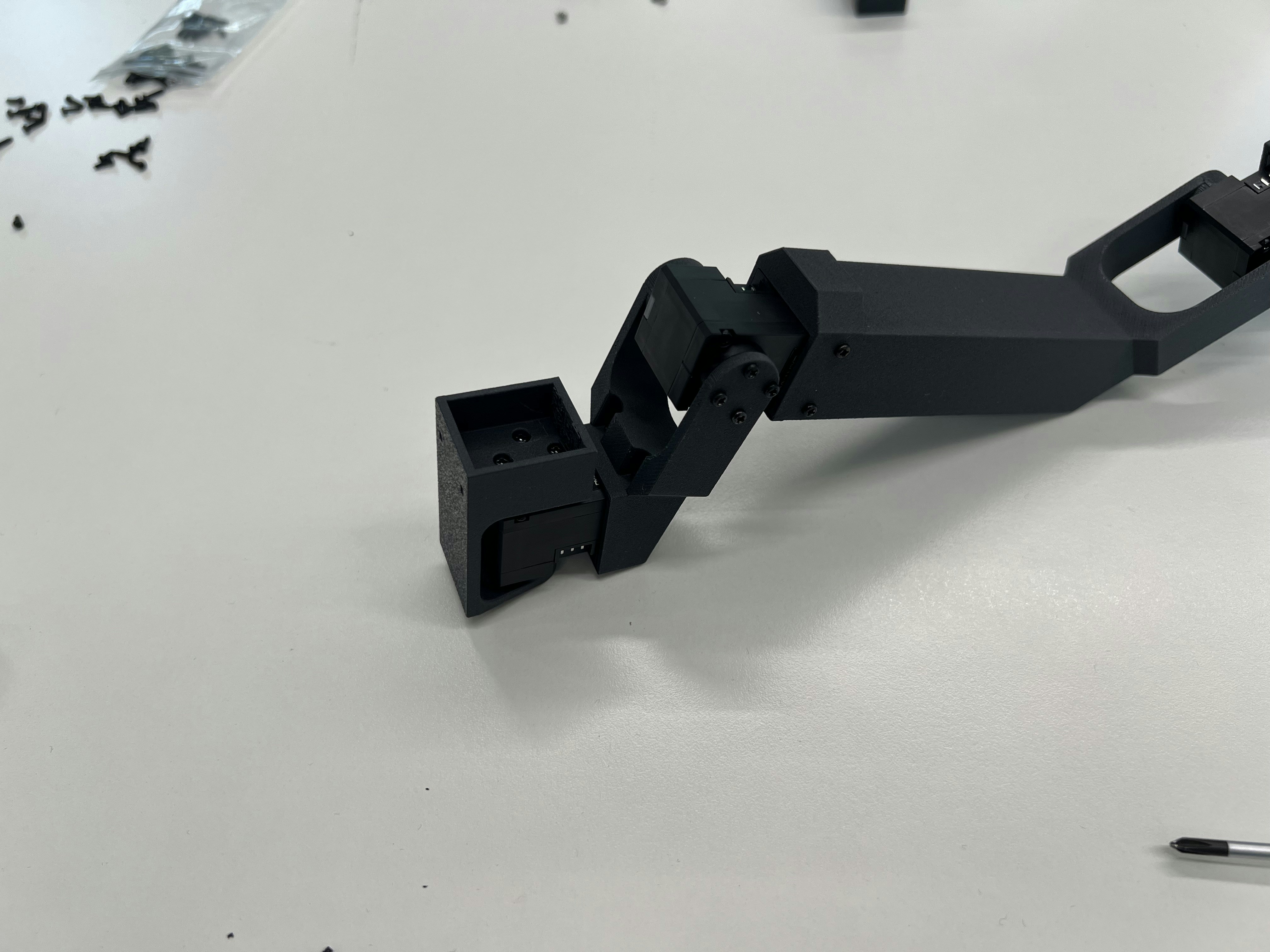
 You have **two choices how to mount the wrist** - either the regular configuration (left) or a configuration which is meant for top-down mounting and operation of TRLC-DK1 (right). For the second one you need to print **link4-5-flipped.stl**.
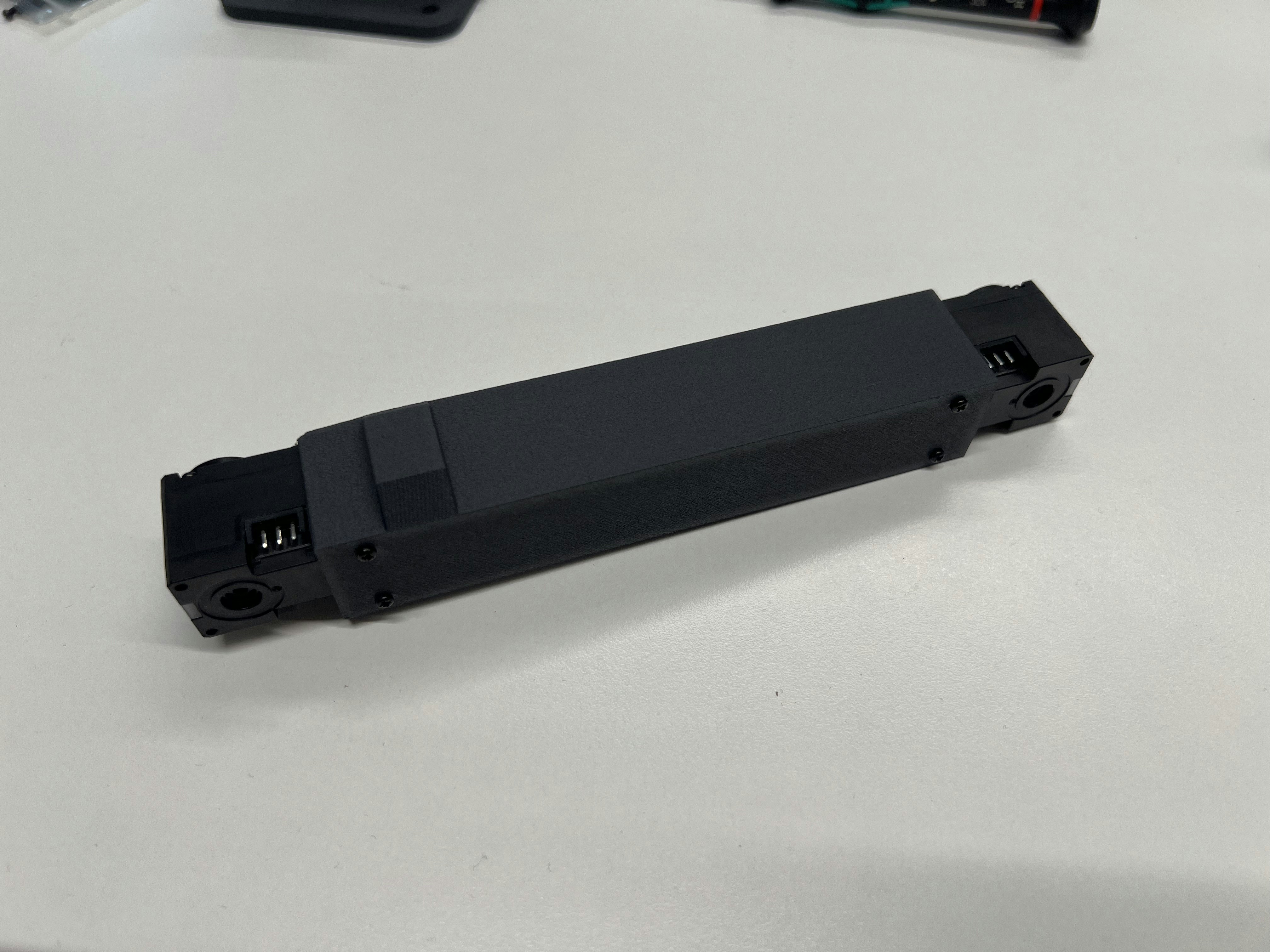
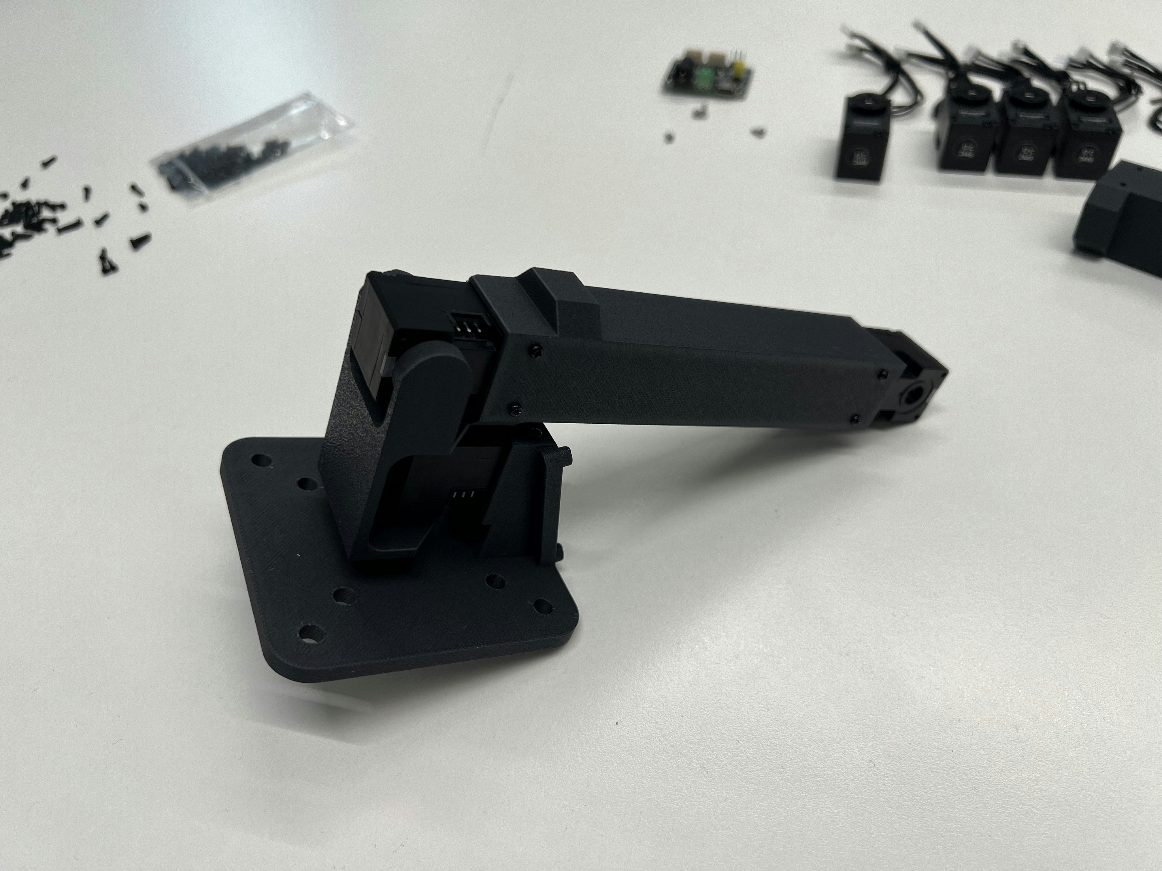
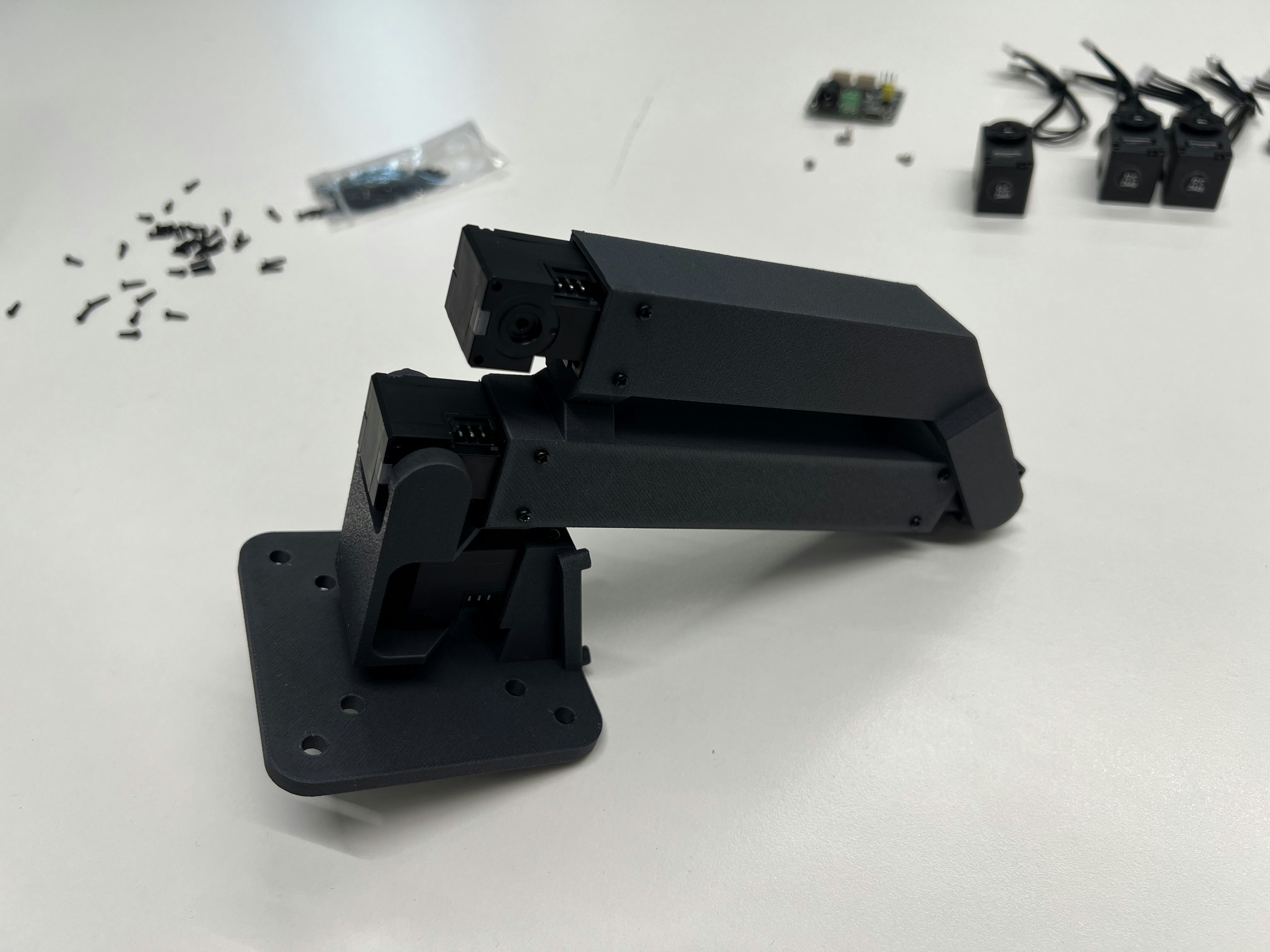
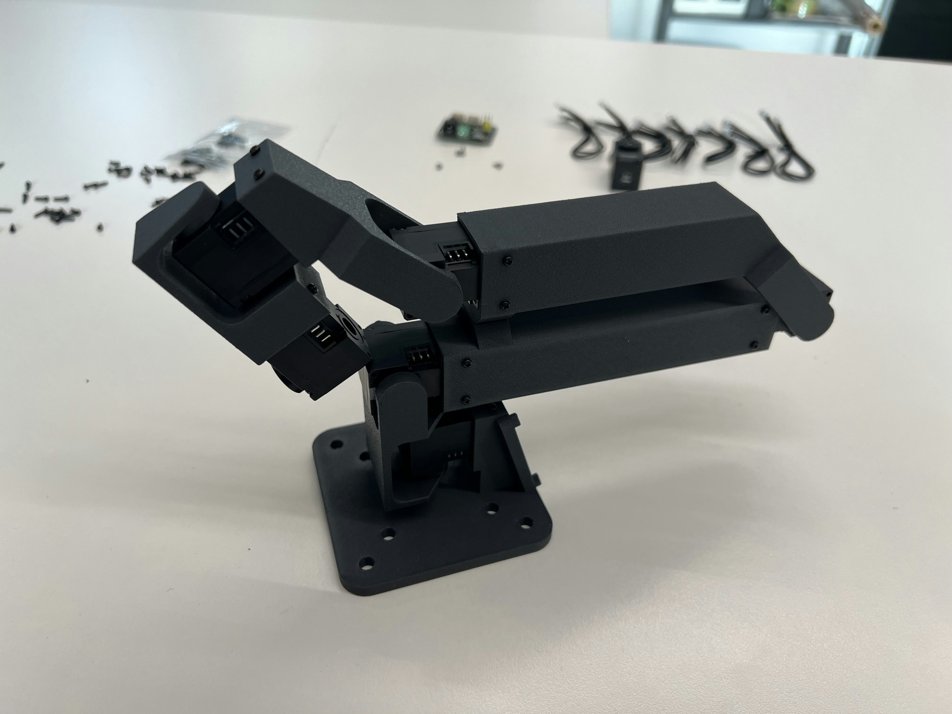
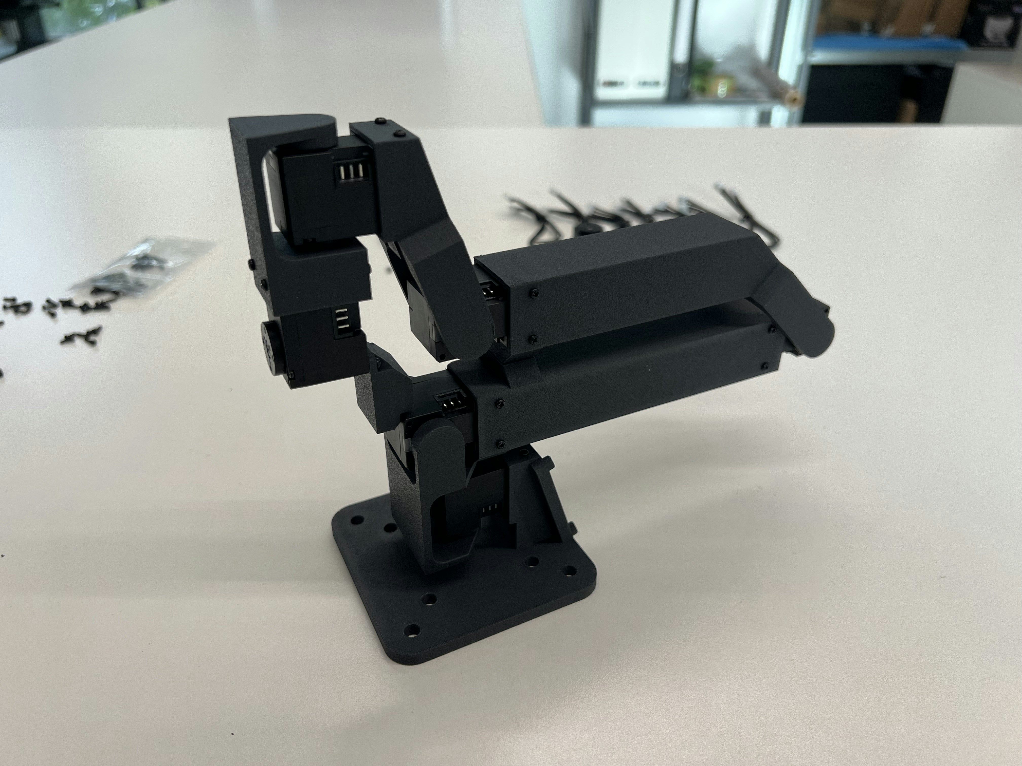
 Continue assembly as shown:
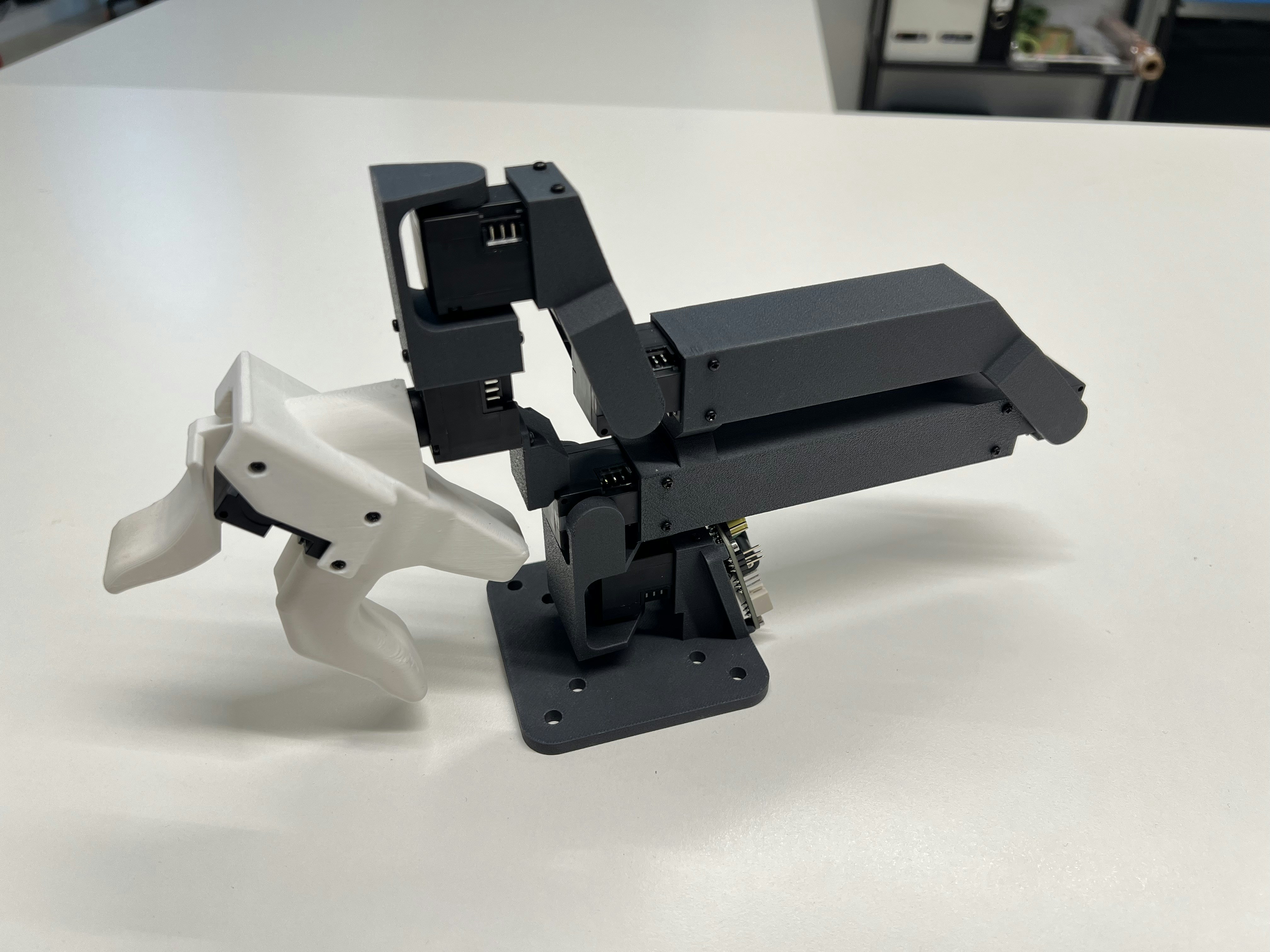
 Mount the GELLO handle:
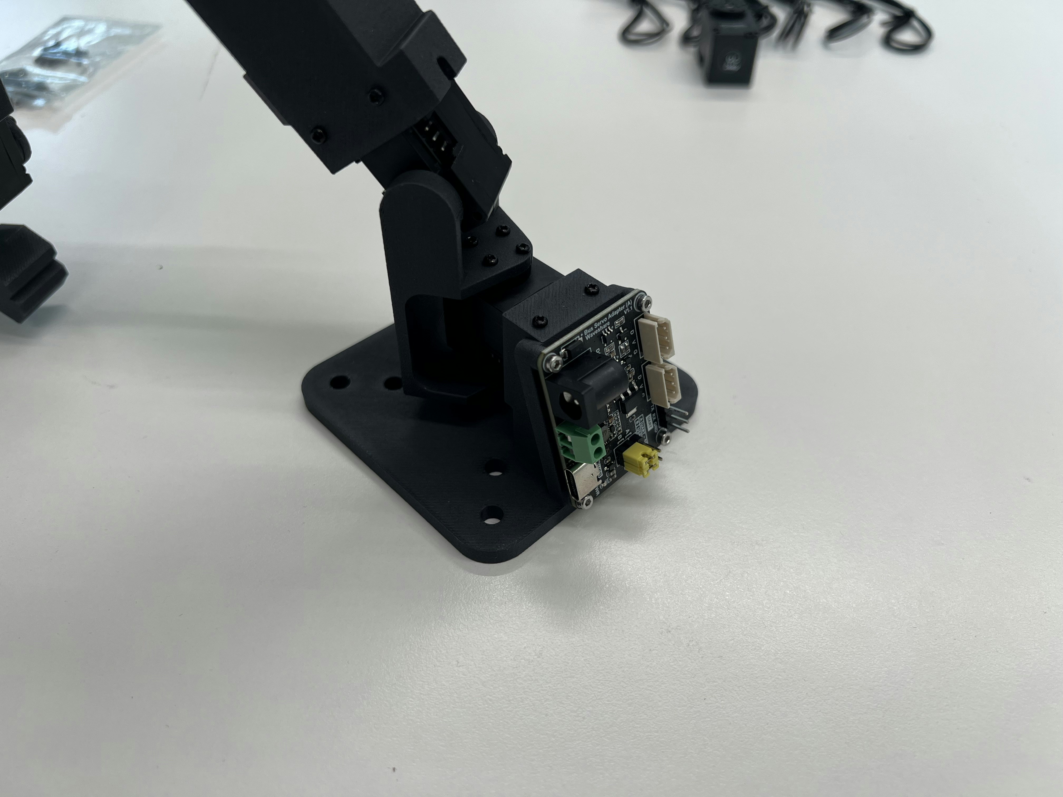
 Mount the driver board:
 ## Configuration
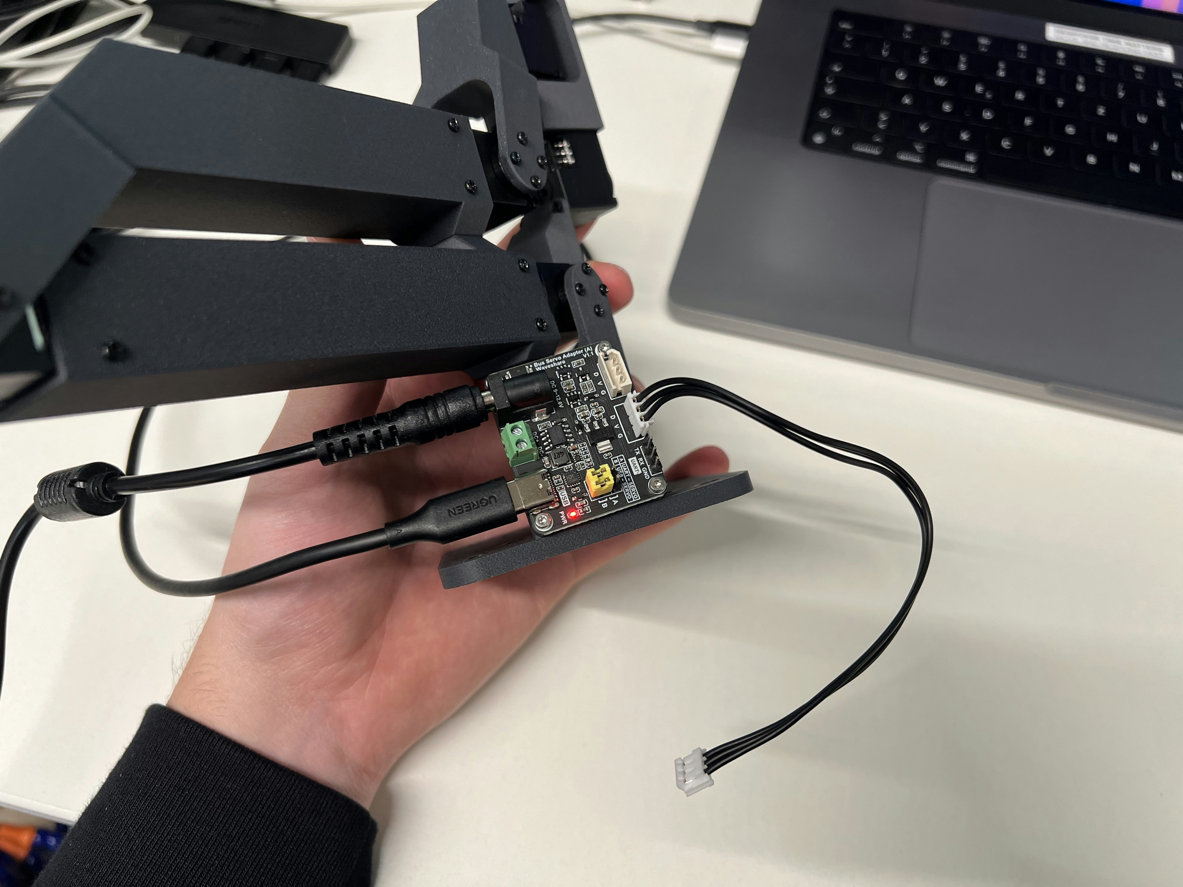
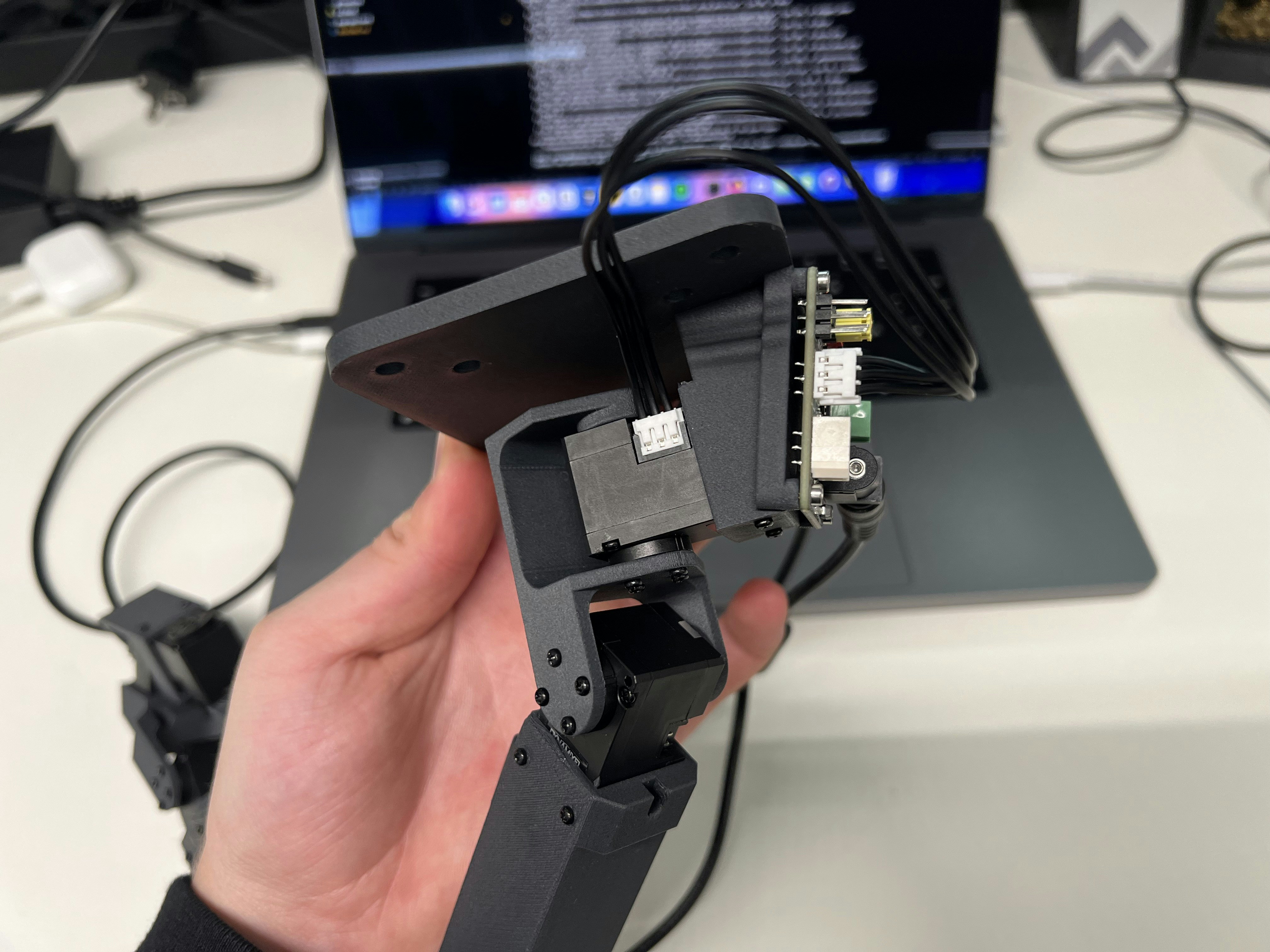
Connect the power supply, a USB-C cable, and one Dynamixel cable:
## Configuration
Connect the power supply, a USB-C cable, and one Dynamixel cable:
 After installing [our fork of LeRobot](https://github.com/robot-learning-co/lerobot) and checking out `trlc-dk1` as branch, run the following to identify the port for the bus driver board:
```
lerobot-find-port
```
To start the motor configuration run the following command:
```
lerobot-setup-motors --teleop.type dk1_leader --teleop.port YOUR_PORT
```
Follow the instructions and connect one motor at a time like so:
After installing [our fork of LeRobot](https://github.com/robot-learning-co/lerobot) and checking out `trlc-dk1` as branch, run the following to identify the port for the bus driver board:
```
lerobot-find-port
```
To start the motor configuration run the following command:
```
lerobot-setup-motors --teleop.type dk1_leader --teleop.port YOUR_PORT
```
Follow the instructions and connect one motor at a time like so:
 The final step is to connect all motors in a daisy-chain:
Due to hardware inaccuracies you might need to run
[leader\_offset.ipynb](https://github.com/robot-learning-co/trlc-dk1/blob/main/examples/leader_offset.ipynb).
Place your leader arm in the resting / zero position and run this script to offset every motor to the theoretical zero degree angles.
The final step is to connect all motors in a daisy-chain:
Due to hardware inaccuracies you might need to run
[leader\_offset.ipynb](https://github.com/robot-learning-co/trlc-dk1/blob/main/examples/leader_offset.ipynb).
Place your leader arm in the resting / zero position and run this script to offset every motor to the theoretical zero degree angles.